DIY
Electric Float Switch for Water Tank DIY
This easy to build DIY float switch design is designed for controlling an ATO (Auto Top Off) pump or solenoid. If you can drill a few holes in plastic and put on a few wire nuts, then you can tackle this Auto Top Off System. The design is very simple, which lends it to be very reliable and maybe the best part very cheap.
When I went to put my ATO together, I looked at what what kind of float switches were available for use in aquarium Auto Top Off Systems and was very disappointed. Every system had signigicant drawbacks: Expensive, safety issues, reliability issues, etc. Having been an electronics technician for 5 years, I set out to do things better. I was hoping that I could improve in every aspect of the design. I believe that this design excels in all areas you typcially care about when relying on a part to determine water level in an aquarium or other application.
The main design premise I was looking for was simplicity. Why not try to switch the power (125V) to your devices directly without needing a relay? Is it possible to do this without getting ANY electrical wires anywhere near the water? The answer was yes. And the best part is the materials can be as cheap as $8. In the end you’ll have an inexpensive, safe, and very reliable Auto Top Off System.


Things you’ll need
- Snap Action switch
- 12oz plastic pepsi bottle
- 1/2″ Sched 40 PVC x 2′
- 1″ Sched 26 (thin wall) PVC x 4″
- 3 x Wire nuts
- 2 x 3/4″ Wood screws
- 1 1/2″ stainless steel 6-32 machine screw (bolt)
- 2 stainless steel 6-32 nuts
- 1 stainless steel 6-32 lock nut
- Drill
- Hack saw (to cut PVC)
- Utility Knife
- Heat Gun (optional)
Here is a diagram showing operation:
Advantages of the new switch:
- No electrical wires in water.
- Very reliable switch operation (2,000,000 cycles).
- Critters can’t effect operation.
- No short cycling of pumps/solenoids – 3/16″ water level swing between on and off.
- Deposits/build-up wont effect operation.
- Directly control your 125V AC pump or device.
- No relays.
- No 12V adapters.
- No reed switches or magnets involved.
- Relatively Cheap components.
- Minimal Tools – Minimal Skill level
- Can be wired in series for redundancy.
- No moving parts in the water to be clogged.
- Water level adjustable up to 5″ after installing!
- Corrosion protection since switch enclosure is air tight.
Disadvantages of typical float switches:
- Reed based switches can suffer from magnetized reeds after a few years.
- Reed based switches require a relay and a 12v adapter to run (constant power draw).
- Most need a shroud of some type to keep the snails from clogging them.
- Need maintenance to keep the crud off of and out of them.
- Can create fast recuring pump on/off cycles.
- Are difficult to DIY improve (you usually buy the premade switch and integrate it)
- Safety issues of having electrical wires in or very near the water.
The main disadvantage to a poorly designed or overly complex float switch system is a short lifespan. We are relying on it to keep the system from flooding and the salinity stable. So we are forced to build in redundancy.
The key part of this float switch is a “snap action“, 120V, 3A rated switch. You can not use just any switch for this design. It must be a snap-action switch. Most switches, including reed switches, when used in a float configuration suffer from short cycling (turning on and off rapidly) the pump or solenoid. Short cycling severly shortens pump or solenoid lifespan not to mention wastes power. Also short cycling a RO membrane will shorten life and cause significant TDS creep which isn’t good for your membrane or your tanklife.
The “Snap action” forces the switch to change position completely before the internal contacts are toggled (from off to on, or on to off). The switch plunger has to move a fixed amount before it changes state. This ensures that the water level will move a fixed amount before the switch changes. This eliminates short cycling and lets your RO unit run for an extended period lessening TDS creep issues.
I found a waterproof snap action switch which I think will work well in a corrosive environment. I don’t intend to use it underwater although it looks like you could. The point here it to keep the wires (and mechanics) away from the water. The switch internal can’t corrode from salt spray if the internals are sealed.
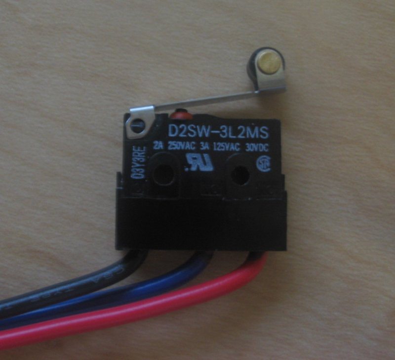
The switch i used is an Omron Part # D2SW-3L1MS. The one shown is the D2SW-3L2MS. The only difference is the ~1MS doesn’t have the roller on the end of the arm. I purchased mine from amazon.
How to install float switch?
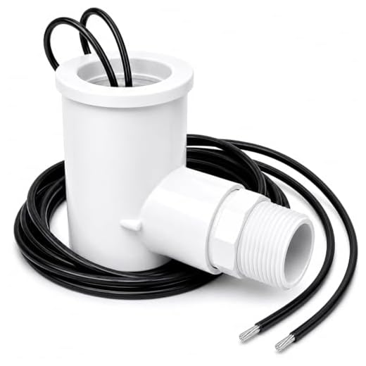
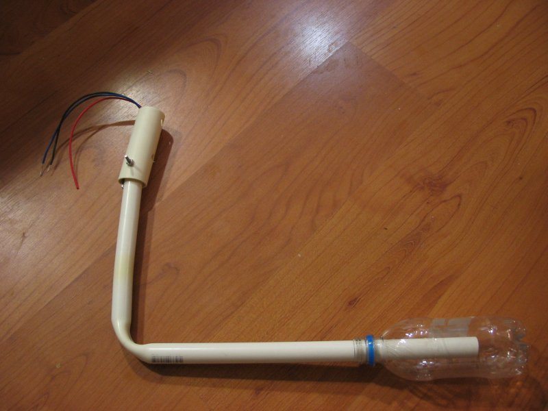
Here’s the fully assembled unit ready for mounting and wiring.
Cut the switch slot
Starting with the 1/2″ schedule 40 pipe cut off a length around 24″. Drill using a 7/32″ bit around 4 holes adjacent to one another until you have a slot long enough to house the switch.
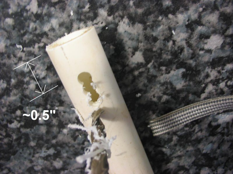
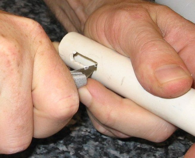
Using a utility knife cut out the slot so that the switch fits very snuggly in the slot. I made is so my switch is so tight in there, I don’t have to glue it in. It will just sit in the slot and wont wiggle out.
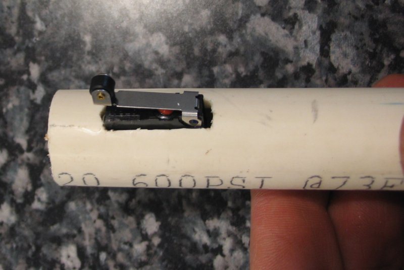
Here is the switch in the slot when you are done. Note: I used some images using the switch with a different lever arm, but the principle is the same.
Make the switch hinge:
Next drill a 5/32″ hole through the short end of the pipe as close to the switch as possible.
Here you can see the bolt going through the hole in the 1/2″ pipe in fully assembled shot. Sorry, I didn’t take a picture of this process as I went.
Make the float switch mount
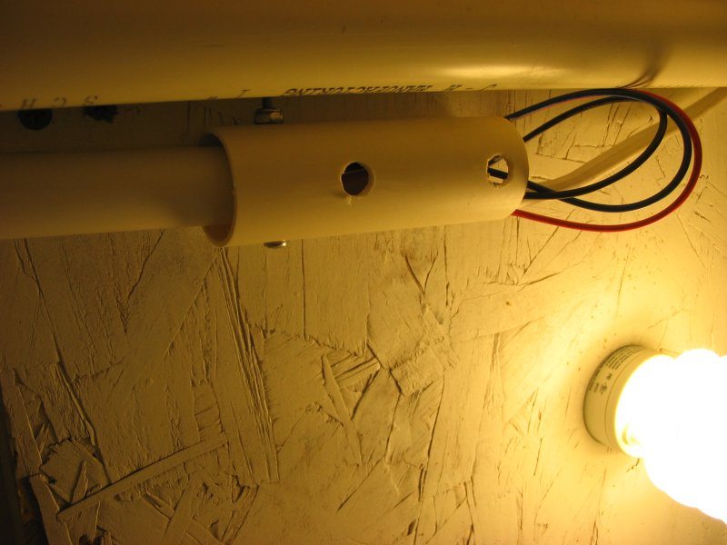
Next drill two 3/16″ holes through both sides of the 1″ pvc. Then on one side of PVC, widen the holes using a 3/8″ drill so that a screwdriver tip can fit through the hole to drive in a screw. The following image shows the side with the widened holes. You can see the smaller hole on the other side for screw mounting. Notice that on one side i didn’t drill very close to the end of the pipe, so that the float arm won’t be in the way of putting a screw through the 3/16″ hole.
This isn’t the same pipe but it shows the same type of holes.
Attach the arm to the mount
Next you need to drill a 5/32″ hole in the 1″ mounting pipe for the float arm pivot. This isn’t an exact science. It may require some trial an error. I insterted the float arm switch into the pipe just a little and drilled so that when the float arm was parallel with the pipe the switch was closed. When the float arm drops a little the switch opens. It is slightly off center drilled for this to work. Here is the switch closed:
And open
Float Arm Bend
I used a heat gun to heat the PVC until it was soft and then just bent it. It bends pretty easy. Just dip the pipe bend in water after you achieve your desired shape and it will solidify. You could just use a 1/2″ 90 fitting if you don’t want to bend it. But bending was cheaper for me.
I bent the 1/2″ PVC pipe to create a 8 inch lever arm. This results in about 3/16″ water level swing between on and off. Incease the length before the bend for a larger swing in water level.
How to wire float switch?
Insert the 1.2″ long pipe into the 12oz soda bottle. This cool part about this fitting is that it will be so snug that it requires a fair amount of force to get it started. This works out nicely since it holds strong enough not to have to glue it. This means later you can adjust the bottle up or down to change the water level switch point to fine tune it. Use two wood screws to mount the 1″ pipe to the underside of top of your stand. Position the float so that it sits in the return section. When picking the place to mount the ensure that nothing will obstruct the float arm.
The wiring
- Black = common
- Blue = normally open
- Red = normally closed
Hook up the hot line of your outlet through this switch. If you aren’t confident in your electrical skills get someone who is to help you. Use the black and red wires. Hook Hot to Red, switched hot to Black, leave the blue unconnected, but put a wirenut on it for safety. See the data sheet for more wiring info.